When machining on circular cylinder, the engineer draws the feature to be
machined in the "flat" X-Y plane. Then, when sending the CNC program to the
CNC machine to be machined, the machine translates all of the Y coordinates
to the proper A or rotary axis movements. There is a problem with this
translation in that all of the Y transformations are only accurate for one
set of conditions. This is most visible when machining round features. The
round features come out as oval shaped.
This calculator does the calculations for you so that you can adjust your
CAD model to create the proper dimensions. Simply enter the cylinder diameter
you are machining on, the depth of your feature, and then the dimension in the
X direction that you want to machine in the Y direction.
If you are machining a round feature, then the X direction dimension should
be your desired diameter.
Engineering calculations developed by Rich Budek. No compensation is done
yet for the taper of the tool (it's being developed), therefore, use these calculations
as a guide.
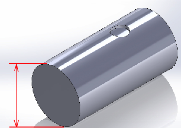
Cylinder Diameter
Cylinder diameter is the diameter of the cylinder that you are machining
on. Sometimes called the "roll diameter". You can use any units you want like
inches, centimeters, etc. As long as you use the same units for ALL the inputs.
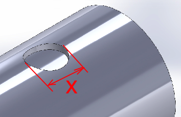
X Direction Dimension
X direction dimension is the measurement in the X direction. The X
direction is in the direction of the axis, in other words, the horizontal
direction of the cylinder.
If you are machining a circle, then enter the diameter of your design.
You can call this the "theoretical" diameter. The diameter in the Y direction
will have to be lengthened and the calculations will tell you what they are.
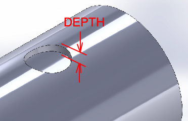
Depth of Feature
Depth of the feature is how deep you are machining your feature.
The depth determines how distorted your feature will be. Enter the depth
using the same units you did for your cylinder diameter and X direction
diameter.